Industry Trends
2026-10-16
Content
At a cement plant in Jiangsu Province, an NU2240 in the kiln drive gearbox failed three times in eight months. All three replacements shared the same part number, but only the third supplier's bearing survived past a year. At Shanghai Yinin Bearing & Transmission Company, we see this pattern often: the load rating, cage, material, clearance, and lubrication decide the service life more than the bore size.
Bore size defines the envelope; the basic dynamic load rating C defines the life. Two NU2206 bearings with the same 30 mm bore can differ by more than 10 percent in C because of roller count and raceway geometry. C is the load under which 90 percent of an identical group completes one million inner-ring revolutions without fatigue. C0 controls how much shock the bearing absorbs before the raceways deform.
The chart below shows why the load ratio dominates. ISO 281 gives the basic rating life as L10 = (C/P)^(10/3) million revolutions. Because of the 10/3 exponent, a 20 percent underestimate of the equivalent load P reduces the calculated L10 life by roughly 45 percent.
For a practical view, read our analysis of cylindrical roller bearings in heavy-duty machinery.
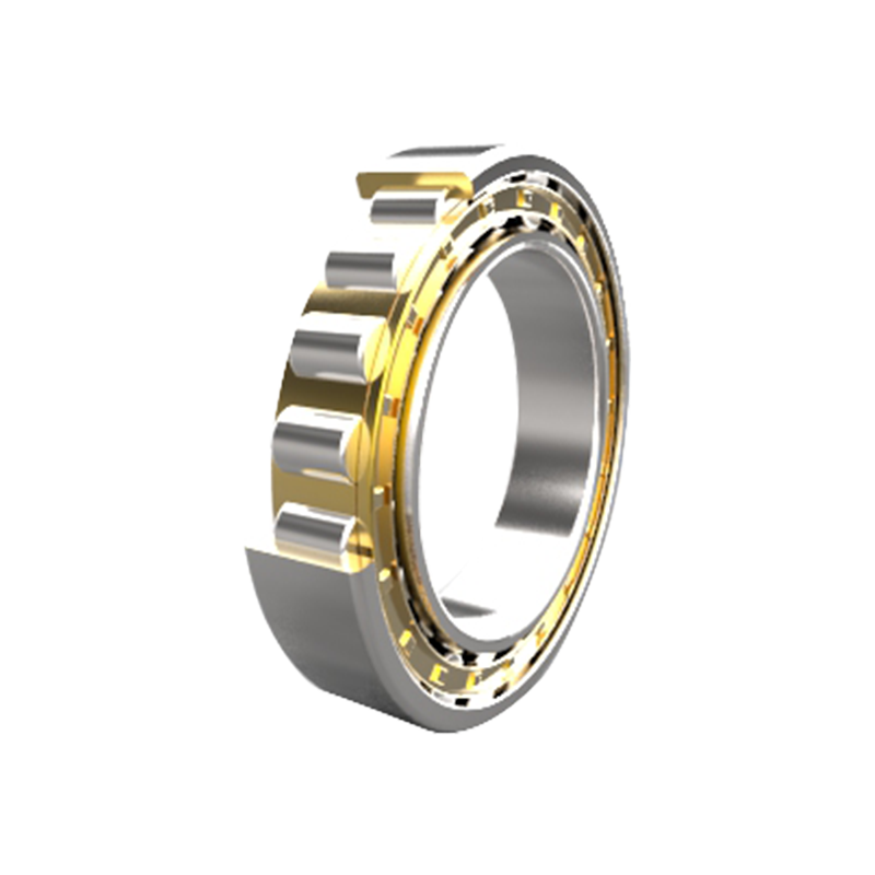 NU200 Series High-Capacity Cylindrical Roller BearingsThis open-design cylindrical roller bearing offers large radial load capacity and rigidity, with free axial movement. It suits heavy loads and high-speed operation, making it relevant for understanding how rib arrangement controls axial freedom.View Product →
The design code decides where the shaft can grow with temperature and where it must stay fixed. Cylindrical roller bearings are line-contact bearings: the rollers touch both raceways along a line, which gives high radial rigidity but accepts almost no axial load and almost no misalignment. NU, N, NJ, NUP, and NF describe the rib arrangement that controls axial freedom.
| Design code | Rib arrangement | Axial displacement | Typical role |
| NU | Ribs on both sides of the outer ring | Free in both directions | Floating bearing |
| N | Ribs on both sides of the inner ring | Free in both directions | Floating bearing |
| NJ | Outer ribs plus single inner rib | Locating in one direction | Semi-locating bearing |
| NUP | Outer ribs plus one inner rib and loose ring | Fixed in both directions | Locating bearing |
| NF | Inner ribs plus single outer rib | Locating in one direction | Semi-locating bearing |
For the locating position in a heavy gear drive, NUP is the classic choice because it fixes the shaft axially in both directions. NJ locates in one direction only and suits arrangements where the opposite thrust is carried elsewhere. Under very heavy combined loads, add a separate thrust bearing for the axial share.
NJ2200 Series Single-Rib Cylindrical Roller BearingsFeaturing a single-rib inner ring and double-rib outer ring, this bearing provides high radial load capacity and axial positioning in one direction. It suits gearboxes and heavy machinery, aligning with the discussion on locating positions and cage requirements.View Product →The cage is a load-bearing structure, not a spacer. Under vibration, shock, or reversing torque, a weak cage deforms, roller spacing becomes irregular, and the bearing moves from noise to seizure. Three families dominate heavy-load specifications: machined brass, stamped steel, and polyamide.
Machined brass cage
Stamped steel or polyamide
Under continuous heavy radial load, a two-piece machined brass cage guides each roller in its own pocket and keeps spacing uniform while the rings deflect elastically. A stamped steel cage is lighter and suits higher speeds with moderate loads. Avoid polyamide above 120°C or with aggressive synthetic oils.
Material grade decides whether the bearing survives impact, not whether it carries steady radial load. Most cylindrical roller bearings are through-hardened SAE 52100 chromium steel at 58 to 62 HRC, adequate for continuous heavy load. Where impacts are routine, as in construction equipment and mining shovels, use case-carburized steel: a tough core with a hard case that tolerates momentary overloads without cracking. Our construction industry page covers these applications in detail.
Internal clearance is consumed by the interference fit and by the inner ring running hotter than the outer ring. If the operating clearance reaches zero, rollers wedge, skid, and smear the raceways. That is why C3 is the default for heavy loads, and C4 is reserved for severe shock or high temperature differentials.
| Operating condition | Shaft fit | Housing fit | Clearance grade |
| Rotating inner ring, continuous heavy radial load | m6 / p6 | H7 | C3 |
| Rotating inner ring, shock or reversing load | p6 | J7 | C3 or C4 |
| Stationary inner ring, rotating outer ring | g6 / h6 | M7 / N7 | CN or C3 |
| Locating position with NUP under heavy load | k6 / m6 | N6 / P6 | C3 |
Lubrication is the final load-carrying component. For oil-lubricated gearboxes under heavy radial load, ISO VG 320 with EP additives is a common start; low-speed, heavy-shock positions use ISO VG 460 or 680. ISO 281 adjusts life with the viscosity ratio kappa. Target a kappa between 2 and 4, and confirm the calculated film thickness exceeds the composite surface roughness.
NUP200 Series Double-Ribbed Cylindrical Roller BearingsThis separable design with two side retaining rings handles radial loads and small axial loads, offering high rigidity and easy installation. It fits the context on locating positions in gear drives and the final specification decisions for bearing selection.View Product →A reliable specification is five sequential decisions, taken in order so no generic fit is forced onto an unquantified load case.
C is the basic dynamic load rating, the load under which 90 percent of an identical bearing group survives one million revolutions. C0 is the basic static load rating, the load that produces permanent deformation of 0.0001 times the roller diameter at the heaviest contact. Use C for fatigue-life calculations and C0 for the static safety factor s0 = C0/P0 under shock conditions.
Use NUP where the shaft must be located axially in both directions, which is the standard fixed-position arrangement in a gear drive. Use NJ where location is needed in one direction only and the opposite thrust is carried by another component, because the NJ assembly is simpler and has no loose rib ring.
An interference fit on the shaft and a warmer inner ring remove a large part of the nominal clearance during operation. If the operating clearance approaches zero, rollers wedge and skid, causing smearing and rapid failure. C3 provides a safety margin for fitted, warm-running arrangements, and C4 is reserved for shock loads and high temperature differentials.
Only if alignment is controlled. A standard cylindrical roller bearing accepts roughly 1 to 2 arc-minutes of misalignment, while a spherical roller bearing handles about 1 degree or more. If the shaft deflects under load, a cylindrical roller bearing edge-loads and fails quickly despite a higher radial rating. Verify housing and shaft alignment before making the change.
Our provided products
Contact Us
Tel: +86-13916786238
Fax: +86-21-68551629
Email: [email protected]
Add: HuangXu Industrial Area, DanTu, ZhenJiang city, JiangSu Province, China
Industries


 English
 日本語
日本語
 Français
 Español