Industry Trends
2025-07-19
Content
Angular contact ball bearings are precision components designed to handle combined radial and axial loads. Unlike radial bearings, their unique construction allows them to support forces at an angle (the "contact angle"), which enhances performance in high-speed or heavy-load applications. The key components include inner and outer rings, balls, and a cage that maintains ball spacing.
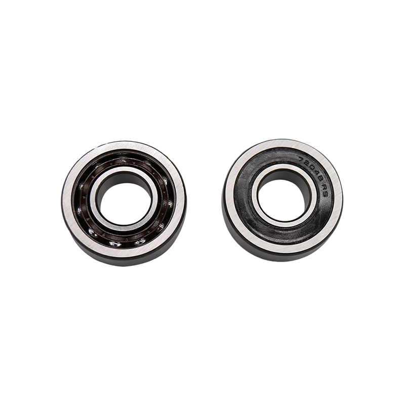
7200 Series Single Row Angular Contact Ball Bearings
The angled contact surfaces create a force triangle that resolves loads efficiently. For example:
| Contact Angle | Radial Load Capacity | Axial Load Capacity |
|---|---|---|
| 15° | High | Moderate |
| 25° | Balanced | Balanced |
| 40° | Moderate | High |
High-speed operations demand bearings with low friction, heat resistance, and precise tolerances. The optimal design combines several critical factors:
Ceramic balls (silicon nitride) reduce centrifugal forces by 40% compared to steel in ultra-high-speed scenarios. However, full ceramic bearings may lack the toughness needed for shock loads.
While both bearing types use balls, their applications differ significantly:
| Parameter | Angular Contact | Deep Groove |
|---|---|---|
| Axial Load Capacity | High (unidirectional) | Low |
| Radial Load Capacity | Moderate | High |
| Speed Rating | Higher (better heat dissipation) | Lower |
Choose angular contact when:
Accurate load calculations prevent premature failure. The basic dynamic load rating (C) and static load rating (C0) from manufacturer catalogs form the basis, but real-world conditions require adjustments.
P = XFr + YFa
Where:
X = radial factor (0.35-1.5)
Y = axial factor (0.57-2.3)
Values depend on contact angle and bearing series
L10 = (C/P)^3 × 1 million revolutions
For 90% reliability. Harsh environments may require L10a calculations with contamination factors.
Preloading eliminates internal clearance to enhance system stiffness and reduce vibration. Common methods include:
Dial indicators measure axial displacement (typically 0.02-0.08mm for medium bearings). Excessive preload increases friction; insufficient preload allows play.
Recognizing failure patterns helps implement corrective actions:
Surface pitting indicates normal wear (L10 life expiration) or contamination. Compare with:
| Symptom | Normal Fatigue | Contamination Damage |
|---|---|---|
| Pit Shape | Circular | Irregular |
| Location | Load zone | Random |
Discoloration (blue/brown) suggests inadequate lubrication or excessive preload. Infrared monitoring helps detect early-stage issues.
Our provided products
Contact Us
Tel: +86-13916786238
Fax: +86-21-68551629
Email: [email protected]
Add: HuangXu Industrial Area, DanTu, ZhenJiang city, JiangSu Province, China
Industries
 English
 日本語
日本語
 Français
 Español


